Applications for Optical thickness Monitoring(광학 박막 두께 모니터링의 응용)
1. Introduction
Coating of optical parts is an indispensable process in optical products, which can greatly improve the performance of optical parts, not only improve the accuracy of various optical instruments, but help us improve more excellent digital products as well. Therefore, the requirements for the coating process are getting very high, and the precise control of the film thickness is one of the important parts.
At present, there are many kinds of methods of film thickness monitoring, such as quartz crystal oscillation method, single-wavelength extremum method, wide-band spectrum method and so on. The wide-band spectrum method can provide the film to monitor the irregular film system in a wide wavelength range, while the extremum method generally requires a regular film layer. So, the wide-band spectrum method has been gradually applied to the application of film thickness monitoring system.
Wide-band spectrum monitoring system often used two kinds of optical path, Vertical path for Transmission way, or Inclined optical path of Reflection way.
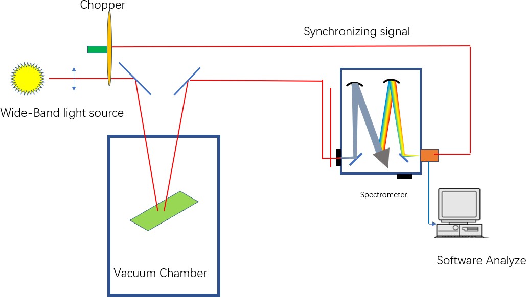
Reflection way:

Fig.1: Schematic diagram of reflective wide-band spectrum monitoring system
When coating, the inside of the vacuum chamber is a bright environment, the stray light will be measured at the same time when the signal light is received, which will decrease the signal-to-noise ratio(SNR). Therefore, in order to eliminate the influence of stray light, scientists introduced a chopper to modulate the signal light, and at the same time, the chopper output a synchronization signal to trigger the detector.
So there will be two signals: 1, signal light + stray light,
2. Stray light only.
In the monitoring process, the stray light can be effectively removed by subtracting the two signals.
The signal will be received in the grating spectrometer, via Fibre. If CCD is applied after the spectrometer, it’s very easy for us to get a wide spectrum in one shot(even can get several hundred nm)

Fig.1: Schematic diagram of transmission wide-band spectrum monitoring system
Similar to the reflection way, the chopper also modulates the probe light to pulsed light, which is converted into parallel light by the lens group, and the transmission spectrum is obtained after passing through the sample. The probe light is introduced into the spectrometer by optical fiber for analysis. At the other end of the optical path, through the imaging system, the interior of the vacuum chamber can be monitored with a Monitor camera.
We can use CCD as the detector for wide rang capture, or PMT for scanning. These two kinds of detectors has its own advantages, CCD can get wide range spectrum in a short time, while the sensitivity of PMT is much higher, and easy to find the change of weaker signal.
In Recent years, scientists begins to focus on film thickness monitoring in near infrared range.

Fig.3:Schematic diagram of film thickness monitoring system in near infrared range
The spectrometer system and InGaAs detector are used in this diagram. With Labview software, the scientists make a in-situ near infrared film thickness monitoring system.
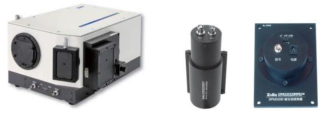
Zolix provide all kinds of spectrum capturing system, including PMT (for Visible range), InGaAs detector(for NIR range)

Fig.4:Zolix Spectrometer,PMT and InGaAs Detectors And also we have spectrometer with CCD, Omni-λ3008i-iVacN

Fig.5: Omni-λ3008i-iVacN
| resolution(nm) | 0.11@1800 groove; 0.37@600 groove |
| Focal Length(mm) | 320 |
| Relative aperture | F/4.2 |
| Stray Light | 1X10⁻⁵ |
| Slit | 0.01-3mm adjustable |
| Dimension of grating,mm | 68X68 |
| Turrent | 3 |
| CCD pixels | 2000×256 |
| Size of pixel | 15×15 |
| Full capacity | 300,000e- |
| Maximum FPS (spectra/s) | 181 |
| Readout noise(e,typical) | 3e- |
| Dark current | 0.1 e-/pixel/s@-60℃ |
Table 1:Specification of Omni-λ3008i-iVacN
Reference:
- Zhang Cheng, Lu Weiqiang,Wang Yongtian, Hao Qun,Chinese Journal Of Scientific Instrument,24(4),85 (2003).
- Ren Hao, Wang Qiaobin, Luo Yuqiang,LiKangye,Laser & Optoelectronics Progress,47,053101 (2010).
- Suotao Dong, Xiuhua Fu, Cheng Li, Coatings, 12,7782(2022).
1. 서론 (Introduction)
광학 부품의 **코팅(Coating)**은 광학 제품 제조에 있어 필수 불가결한 공정입니다. 이는 광학 부품의 성능을 대폭 향상하고 각종 광학 기기의 정밀도를 높일 뿐만 아니라, 더 우수한 디지털 제품을 개발하는 데 기여합니다. 따라서 코팅 공정에 대한 요구 사항은 점점 더 엄격해지고 있으며, 그중에서도 **박막 두께(Film thickness)**의 정밀한 제어는 가장 중요한 요소 중 하나입니다.
현재 박막 두께를 모니터링하는 방법으로는 수정 진동자법(Quartz crystal oscillation method), 단파장 극치법(Single-wavelength extremum method, Turning point monitoring), 광대역 분광법(Wide-band spectrum method) 등 다양한 방식이 존재합니다. 광대역 분광법은 넓은 파장 대역에서 비주기적(Irregular) 박막 시스템을 모니터링할 수 있는 반면, 극치법은 일반적으로 규칙적인 박막 층을 요구합니다. 이러한 장점 덕분에 광대역 분광법은 박막 두께 모니터링 시스템에 점차 널리 적용되고 있습니다.
광대역 분광 모니터링 시스템은 주로 투과(Transmission) 방식을 위한 수직 광로 또는 반사(Reflection) 방식을 위한 경사 광로, 이 두 가지 광학 경로를 사용합니다.
2. 반사 방식 (Reflection Way)
(그림 1: 반사식 광대역 분광 모니터링 시스템 구성도)
코팅 공정 중 진공 챔버(Vacuum chamber) 내부는 매우 밝은 환경이므로, 신호광(Signal light)을 수신할 때 **미광(Stray light)**이 함께 측정되어 **신호 대 잡음비(SNR)**를 저하시킬 수 있습니다. 따라서 과학자들은 미광의 영향을 제거하기 위해 **광 초퍼(Chopper, 광단속기)**를 도입하여 신호광을 **변조(Modulate)**하고, 동시에 초퍼에서 검출기를 트리거(Trigger)하기 위한 동기 신호(Synchronization signal)를 출력하도록 설계했습니다.
이에 따라 두 가지 신호가 발생합니다:
- 신호광 + 미광
- 미광 (Stray light only)
모니터링 과정에서 첫 번째 신호에서 두 번째 신호를 감산(Subtracting)함으로써 미광을 효과적으로 제거할 수 있습니다. 신호는 광섬유(Optical fiber)를 통해 **회절격자 분광기(Grating spectrometer)**로 전달됩니다. 분광기 후단에 CCD를 적용하면 한 번의 촬영(One-shot)으로 넓은 스펙트럼(수백 nm 대역)을 매우 쉽게 획득할 수 있습니다.
3. 투과 방식 (Transmission Way)
(그림 2: 투과식 광대역 분광 모니터링 시스템 구성도)
반사 방식과 유사하게, 초퍼가 **탐침광(Probe light)**을 펄스광으로 변조합니다. 이 빛은 렌즈군(Lens group)에 의해 **평행광(Parallel/Collimated light)**으로 변환되어 시료를 통과한 후 투과 스펙트럼을 형성합니다. 탐침광은 분석을 위해 광섬유를 통해 분광기로 입사됩니다. 광로의 반대편에서는 이미징 시스템을 통해 모니터링 카메라로 진공 챔버 내부를 관찰할 수 있습니다.
광대역 포착을 위해서는 CCD를, 스캐닝(Scanning) 방식을 위해서는 **PMT(광전자 증배관)**를 검출기로 사용할 수 있습니다. 이 두 검출기는 각각의 장점이 있습니다.
- CCD: 짧은 시간 안에 넓은 대역의 스펙트럼을 획득할 수 있습니다.
- PMT: 감도(Sensitivity)가 훨씬 높아 미약한 신호의 변화를 감지하기에 유리합니다.
4. 근적외선(NIR) 영역 응용
최근 과학자들은 근적외선(Near Infrared, NIR) 영역에서의 박막 두께 모니터링에 주목하고 있습니다.
(그림 3: 근적외선 영역 박막 두께 모니터링 시스템 구성도)
이 시스템 구성도에서는 분광기 시스템과 InGaAs(인듐갈륨비소) 검출기가 사용되었습니다. 연구원들은 Labview 소프트웨어를 활용하여 현장(In-situ) 근적외선 박막 두께 모니터링 시스템을 구축했습니다.
Zolix는 가시광선 영역을 위한 PMT, 근적외선 영역을 위한 InGaAs 검출기를 포함한 모든 종류의 스펙트럼 포착 시스템을 제공합니다.
(그림 4: Zolix 분광기, PMT 및 InGaAs 검출기)
또한 CCD가 장착된 분광기 모델인 Omni-λ3008i-iVacN도 제공합니다.
(그림 5: Omni-λ3008i-iVacN)
표 1: Omni-λ3008i-iVacN 상세 사양
참고 문헌 (References)
- Zhang Cheng, Lu Weiqiang, Wang Yongtian, Hao Qun, Chinese Journal Of Scientific Instrument, 24(4), 85 (2003).
- Ren Hao, Wang Qiaobin, Luo Yuqiang, Li Kangye, Laser & Optoelectronics Progress, 47, 053101 (2010).
- Suotao Dong, Xiuhua Fu, Cheng Li, Coatings, 12, 7782 (2022).
